Design Models · Axiom Turbine

VLJ Design Space · System simulation

Design models for system simulation.

An engine is only as good as the aircraft it flies in. These five aircraft exist to test our engines. Each is a complete preliminary design, with geometry, weights, drag and fuel, so we can fly an engine through a whole mission and see what an operator would see: climb, ceiling, fuel burn, range and runway length.

Together they cover the main ways a small turbofan is installed: on the rear fuselage, over the wing, buried in the fuselage, under the wing of a freighter and in a pod on a cargo drone.

Aircraft models
5
Installation layouts
5
Take-off mass range
0.65–8.6t
Cruise up to
FL450

The models

Five aircraft, one purpose.

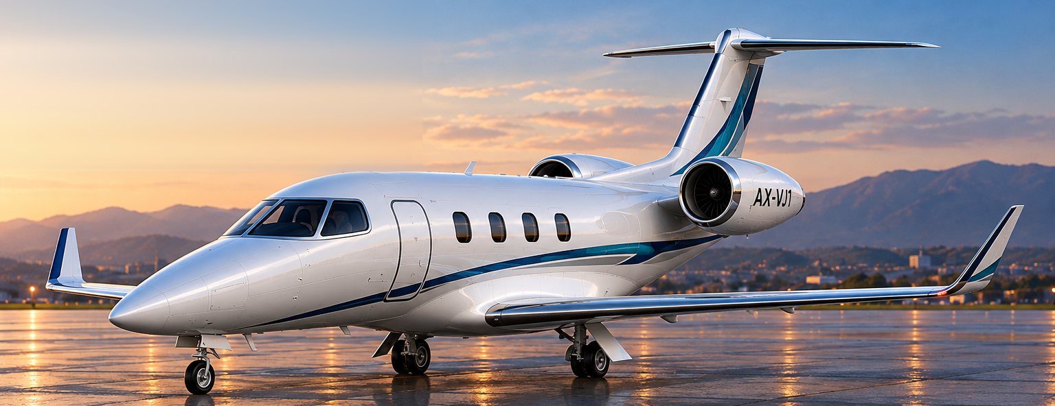
Concept render of the AX-VJ1
AX-VJ1

Twin jet, engines on the rear fuselage

Our reference aircraft: a single-pilot twin with a carbon-fibre cabin and two engines on short pylons behind it. It is the baseline every engine change is measured against, and the first aircraft to fly each new issue of our A7 engines in simulation.

Seats
Pilot + 4
Max take-off mass
4,900 kg
Cruise
FL450 · Mach 0.70
Range, 4 passengers
≈ 2,670 km
Take-off field
≈ 990 m
Engines
2 × Axiom A7 family

What we simulate with it: Thrust lapse and fuel burn from climb to FL450, and the rear-fuselage intake at high angle of attack.
AX-VJ1B2

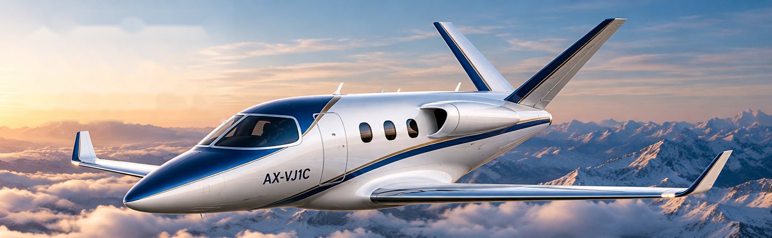
Twin jet, engines over the wing

The same class of twin with the engines on pylons above the wing. Moving the engines off the fuselage frees about one metre of pressurised cabin, and a laminar-flow wing section trims the drag.

Seats
Pilot + 4
Max take-off mass
4,900 kg
Cruise
FL450 · Mach 0.70
Range, 4 passengers
≈ 2,620 km
Cabin
≈ 1 m longer
Engines
2 × Axiom A7 family

What we simulate with it: Installed thrust with the nacelle in the wing’s flow field, and engine-out yaw with wider engine spacing.

Concept render of the AX-VJ6
AX-VJ6

Six-seat single-engine jet

A six-seat jet built for the mission of the fast single-engine turboprops, flown higher and faster. One engine is buried in the tail behind the cabin, with a V-tail above the jet and a laminar-flow wing.

Seats
Pilot + 5
Max take-off mass
4,000 kg
Cruise
FL430 · Mach 0.60
Range, 6 people
≈ 2,500 km
Take-off field
≈ 900 m
Engine
1 × Axiom A8 family

What we simulate with it: Block time against today’s fast turboprops on the same trip, and the buried engine’s intake behaviour.

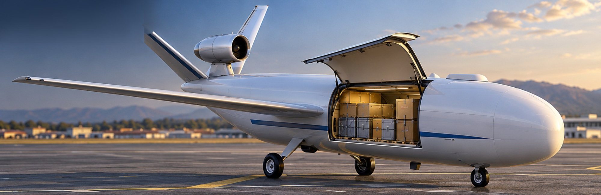
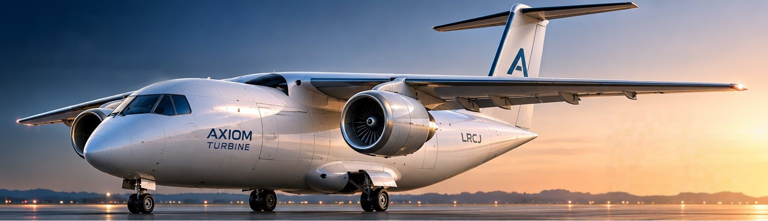
Concept render of the LRCJ
LRCJ

Light regional cargo jet

A single-pilot freighter for regional express cargo: three standard LD3 containers or 2.5 tonnes, loaded through a large forward door, on two Axiom engines under the wing.

Payload
3 × LD3 · 2.5 t
Max take-off mass
8,618 kg
Cruise
FL410 · Mach 0.60
Range, 1.5 t
≈ 1,870 km
Take-off field
≈ 1,260 m
Engines
2 × Axiom A9 family

What we simulate with it: Engine-out climb and ceiling, and payload-range sensitivity to weight and drag.

Concept render of the AXC-650
AXC-650

Regional express-cargo drone

An uncrewed, remotely supervised civil freighter for time-critical cargo: aircraft spares, medical and laboratory shipments, electronics and premium express. It flies about twice as fast as piston-powered cargo drones, on standard Jet A-1 from regional airports.

Max take-off mass
650 kg
Payload, 1,500 km
235 kg
Cruise
9 km · 459 km/h
Block time, 1,500 km
≈ 3 h 36 min
Cargo hold
1.13 m³
Engine
1 × Axiom AFT-2.1

What we simulate with it: The AFT-2.1 through a full 1,500 km mission, and the best cruise level and speed for the engine.

Figures come from our preliminary design models, not from wind-tunnel or flight test. The jet studies were sized with the earlier issues of our engines and are being re-run with the October 2026 engines. Renders are concept visualisations; these are not aircraft offered for sale. Axiom Turbine designs for civil applications only.

The simulation loop

The engine and the aircraft, judged together.

The loop repeats until the engine and the airframe meet the mission together. Next, we plan to bring our aircraft models into a flight simulator and fly them on our own in-house simulator, so each engine can be judged in realistic flight.

Request the design reports
  1. Engine deckThrust and fuel burn across the flight envelope
  2. InstallationIntake and nozzle effects for the layout being flown
  3. Airframe modelDrag, weights and fuel
  4. Mission simulationTake-off, climb, cruise, descent, reserves and engine-out
  5. Engine optimisationThe results set the next engine iteration